|
International Journal of Bioelectromagnetism Vol. 5, No. 1, pp. 57-60, 2003. |
www.ijbem.org |
|
Application of Impedance Volume Measurement to Implantable Devices Rodney W Salo Basic Research Department, Guidant Corporation, St. Paul, Minnesota, United States of America Correspondence: Rodney Salo, Guidant Corporation,
4100 North Hamline Avenue, St. Paul, MN 55112, United States of America.
Abstract: An ideal ventricular
volume sensor for implantable devices would use standard pacing leads
and electrodes and require only simple calculations. Volume measurements
made from a linear array of four electrodes in the right or left ventricle
of the heart display a reasonably linear relationship between actual
and measured stroke volume. The relationship between left ventricular
chamber volume and volume calculated from impedance measured between
electrodes found in a typical patient receiving Cardiac Resynchronization
Therapy (CRT) was determined with a finite-difference model of Poisson's
equation in a heart with realistic geometry. Using electrodes that
span the left ventricular minor axis, calculated and actual volumes
were linearly related with a correlation coefficient of 0.985 over
a left ventricular volume range of 25 º C 125 ml.
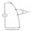
Keywords: Intracardiac Impedance; Implantable Devices; Cardiac Resynchronization Therapy; Volume Sensor; Finite-Difference Model 1. Introduction Biological impedance measurements may be made with two electrodes but are more commonly made with the four-electrode arrangement shown in Fig. 1 in order to minimize electrode polarization effects due to the development of a bilayer charge around an implanted current source. In this arrangement, a constant current source generates a current between an outer pair of electrodes, usually linearly arranged on a catheter, while the potential difference between two inner electrodes is measured by a differential amplifier with a high input impedance.
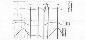
 An intracardiac impedance waveform from a tetrapolar electrode arrangement on a catheter positioned in the right ventricle of a canine heart is displayed in Fig. 2. The impedance waveform demonstrates all of the characteristics expected from an inverted volume waveform (inverted because resistance increases when volume decreases). The electrical potential around a pair of current sources in an irregularly shaped cardiac chamber is highly non-uniform. However, if the inner, sensing, electrodes are reasonably close together compared to their distance from the current sources, the potential gradient or current density can be assumed to be uniform and an equation derived assuming uniform current density can be used. This equation, Eq. 1, sometimes called the cylindrical equation because it was originally derived from a cylindrical geometry capped by equipotential plates, relates the volume of a conductor to the electrical resistance measured across it.
ρ is the resistivity of blood L is the distance between measuring electrodes R is the resistance measured between electrodes.
Figure 2. Tetrapolar right ventricular impedance waveform (lower panel), surface electrocardiogram (upper panel) and right ventricular pressure (middle panel) from a dog. A comparison of left ventricular volumes computed by Eq. 1 to actual volumes in a numerically modeled heart, shown in Fig. 3, reveals two shortcomings: the relationship is nonlinear and there is a volume offset (i.e. there exists a positive measured volume at an actual volume of zero) that is a function of tissue conductivity.
If the baseline impedance, R, is assumed to be much
larger than the variation in impedance during a ventricular contraction,
then it is possible to derive an expression relating the stroke volume
directly to the change in impedance, ΔR. From Eq. 2, the exact relationship
between a resistance and volume change derived from Eq. 1, if ΔR
<< R, then
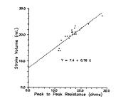
An example of the accuracy of this relationship is shown in Fig. 4.
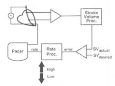
Figure 4. A comparison between right ventricular stroke volume measured by aortic flow and right ventricular peak-to-peak resistance, ΔR, in a dog during an infusion of dobutamine [Salo, 1990] . In practice, it is difficult to predict the slope and y intercept of the relationship between computed and actual volume, but, in many cases, it is sufficient to know that the stroke volume is increasing or decreasing. A simple closed loop system used to control paced heart rate based on stroke volume changes is illustrated in Fig. 5. Figure 5. Closed-loop system to control pacing rate by maintaining a fixed stroke volume [Salo, 1995]. Normally four electrodes, as previously shown in Fig. 1, are required for an impedance measurement. Historically this has required the addition of at least one electrode to the standard bipolar (two electrode) pacing lead and a unique mating connector in the pacing device. These leads are thus incompatible with other devices during future device replacements (e.g. due to a depleted battery) and are therefore at a commercial disadvantage. However, the average CRT patient implant includes as many as six pacing electrodes as shown in Fig. 6, which can also be used for impedance measurements.
Figure 6. Six electrodes positioned in the heart in a heart failure patient undergoing cardiac resynchronization therapy (CRT) are shown as filled circles above. The arrow indicates one possible pair of current sources for left ventricular volume estimation. 2. Methods In order to determine whether impedance measurements made with a subset of the electrodes available in figure 6 could be used to measure left ventricular volume, a three dimensional finite-difference numerical model of a four-chamber heart within a rectangular solid thorax, described previously [Salo, 1986] , was generated with a current source in the right ventricular apex and the left ventricular free wall. Solutions were generated for seven different left ventricular volumes. Since the total tissue mass was kept constant during the simulated contraction, the wall thickness increased as the chamber volume decreased. For each volume the model generated the electrical potential at each node (there were approximately 500,000 nodes with internodal spacing of 2.0 mm). The potentials at a fixed distance of 1.0 cm from each of the current sources were subtracted to generate a measured potential difference corresponding to what would be measured with bipolar pacing leads. The potential difference was divided by the modeled current, in this case 1.0 ampere to simplify calculations, to generate a measured resistance. The chamber volume was then calculated from equation 1 using this resistance. 3. Results The volumes calculated from resistances generated by the finite-difference model are compared to the actual chamber volumes in Fig. 7.
Figure 7. A comparison between the volumes computed (vertical axis) from resistances measured across the left ventricle (from right ventricular apex to left ventricular free wall) and the actual left ventricular volumes (horizontal axis). It appears from the figure that there is a relatively linear relationship (linear correlation coefficient of 0.985) between measured and actual volumes with quite a large volume offset (measured volume at an actual chamber volume of zero). 4. Discussion Ventricular volume is an important parameter in many cardiac conditions such as heart failure and accurate volume measurements are potentially invaluable in monitoring the progression of disease and the impact of therapy. Bioimpedance instrumentation developed for this purpose requires multi-electrode catheters with as many as twelve electrodes and relatively large currents, as much as 20 milliamps. In addition, the accurate determination of volume requires a rather complex algorithm [Salo, 1989]. Inclusion into an implantable device places additional constraints on sensor design. In general, the sensor must be frugal (i.e. require minimal current), rugged and reliable and require no complex calculations. The intracardiac impedance sensor uses standard electrodes and requires only microamperes of current for operation. In addition, measurements made from existing electrodes using equation 1 are sufficient to generate an accurate relative measure of left ventricular volume as shown in Fig. 7. A simple calibration against echocardiographic or other standard volumes to determine the slope and intercept of the relationship appears to be sufficient to determine absolute ventricular volumes. These results must still be tested in animals and patients. References Salo RW. The theoretical basis of a computational model for the determination of volume by impedance. Automedica, 11: 299-310, 1989. Salo RW, O'Donoghue S, Platia EV. The use of intracardiac impedance-based indicators to optimize pacing rate. in Clinical Cardiac Pacing. Ellenbogen KA, Kay GN, and Wilkoff BL, editors. W. B. Saunders Company, Philadelphia, PA, 1995, 234-249. Salo RW, Pederson BD, and HauckJA. The measurement of ventricular volume by intracardiac impedance. in Bioinstrumentation: research, developments and applications. Wise DL, editor. Butterworth, Boston, MA. 1990, 853-891 Salo RW, Wallner TG, and Pederson BD. Measurement of ventricular volume by intracardiac impedance: theoretical and empirical approaches. IEEE Trans Biomed Eng, 33, 189-195, 1986.
© International Society for Bioelectromagnetism
|
||||||||||||||||||||||||||||||||||||||||||||||||||||||||||||||||||||||